|
Main sources: |
US Army Air Force designation: XB-35
Flying Wing Engines: 2 x 3000 hp Pratt & Whitney R-4360-21
Wasp Major First flight: June 25, 1946 (first prototype), June 26, 1947 (second) On April 11, 1941, the USAAF issued a request for proposals for a high-altitude bomber that could carry a 10,000-pound bombload halfway across a 10,000 mile range. Maximum speed was to be 450 mph at 25,000 feet, cruising speed 275 mph, service ceiling 45,000 feet, and a maximum range of 12,000 miles at 25,000 feet. Invitations for preliminary design studies were sent to the Consolidated Aircraft Corporation and to the Boeing Airplane Company. The Consolidated submission was eventually to emerge as the B-36. As part of this project, Northrop was contacted on May 27, 1941 and asked to provide studies of a flying wing proposal as it related to requirements for a range of 8000 miles at 25,000 feet with one ton of bombs, a cruising speed of 250 mph, a service ceiling of 40,000 feet, and a bombload of 10,000 pounds, which were much less demanding than those of the April 11 RFP. In August of 1941, slightly more ambitious requirements were again submitted to Northrop. The Northrop proposal submitted to the AAF in September 1941 was immediately followed by contractual negotiations. In a departure from standard practices, the initial procurement of the flying wing was preceded by a purchase order for engineering data, model tests, and evaluation of reports on the N-1M that had been flight tested since June 1940. The flying wing bomber project (designated NS-9 by the company) received approval for an initial start from the USAAF in September of 1941, following a visit to the Northrop plant by Assistant Secretary of War Robert Leavitt, General Henry H. Arnold, and Major General Oliver P. Echols. The entire order, approved by Secretary of War Henry L. Stimson on 3 October 1941, was covered by Contract W535-ac-21341 which was signed on the 30th. Also included was the purchase of the first N-9M, a 1/3 scale flying mockup of the future B-35. Available records did not reveal the cost of Contract W535-ac-21341, an oversight which by the end of the costly flying wing program proved immaterial. Procurement of the first full scale flying wing, endorsed by Maj. Gen. Henry H. Arnold, Chief of the AAF, on 9 September 1941, came under Contract W535-ac-21920 on 22 November. At the contractor's request, the contract, estimated at $2.9 million, was of the cost plus fixed fee type because, as pointed out by Northrop Incorporated, development of the XB-35 was a large project, involving funds in excess of those available to the company for experimental purposes. In addition, Northrop anticipated that materiel and labor costs would rise significantly before November 1943, when the XB-35 was scheduled for delivery. Besides providing for the first XB-35, Contract W535-ac-21920 included 1 XB-35 mockup, engineering data, plus an option clause covering the purchase of 1 additional XB-35. This option was exercised on 2 January 1942. Northrop quoted a delivery date of April 1944 for the second XB-35, also known as the back up article. The XB-35 was the first Northrop flying wing bomber design. The advantages of a flying wing format were perceived as providing both low drag and high lift, which meant that the XB-35 could carry any weight faster, farther, and cheaper than conventional aircraft. In addition, the use of a flying wing meant that simpler construction methods could be used with fewer structural complications. A flying wing should cost less to build since it was built as a single unit with no added tail or fuselage. A flying wing provides a better weight distribution for the offensive load, since compartments along the entire span could distribute the weight of the bomb load much more evenly. Finally, a flying wing presented a smaller target when seen from fore, aft, or from the side when engaged in either offensive or defensive operations. The initial contract for a single aircraft was awarded in November 1941 and amended to include another in January 1942. Extensive engineering work was necessary (and planned) so Northrop was awarded a contract in October 1941 to build four smaller flying wings under the designation N-9M. It was hoped that flight data gathered from the N-9Ms would speed the development of the B-35 project. Detailed design work on the XB-35 began in early 1942, and the XB-35 full-scale mock-up was approved on July 5, 1942. Although the N-9M data was valuable, the XB-35 program was hampered by a series of delays while engineering problems were solved. An order for 13 YB-35 service test aircraft was placed in September 1942 and another order for 200 production B-35As was placed in June 1943. However, it soon became apparent that the aircraft would not be ready in time for use in WWII. Furthermore, jet bomber prototypes already on the drawing board made the propeller driven XB-35 obsolete before its first flight. The Army decided to continue the B-35 program, but only in test status. The Martin B-35 production order was canceled and the YB-35 order was amended to include conversions to jet powered aircraft (YB-49 and YRB-49A). The development of the XB-35 continued but at a slower pace and the first flight of the XB-35 (S/N 42-13603) wasn't made until 25 June 1946, when the XB-35 Flying Wing lifted majestically from the runway of the Northrop Aircraft Co. and made its maiden flight, with Max Stanley as pilot and Dale Schroeder as flight engineer. On this first flight, the aircraft was flown from Hawthorne to Muroc Dry Lake Army Air Field (now Edwards AFB), a flight lasting 45 minutes. Almost immediately, the flight test program ran into difficulties. Gear box malfunctions and propeller control difficulties caused the XB-35 to be grounded on September 11 after only 19 flights. The second XB-35 (serial number 42-38323) took to the air for the first time on June 26, 1947. Only eight flights took place before Northrop was forced to ground this plane too. The crew of the XB-35 was carried in a crew cabin installed at the center of the wing, with a tailcone protruding beyond the central wing trailing edge. The normal crew was 9--a pilot, copilot, bombardier, navigator, engineer, radio operator and 3 gunners. The pilot sat in the very front of the wing center section (slightly offset to the left of center) underneath a transparent bubble-type canopy. The copilot sat to the right of the pilot and somewhat lower down, and sighted through a set of transparent windows cut into the front of the wing. His visibility, though, was fairly marginal. The bombardier's station was located to the right of the copilot's seat, and the bombardier operated the bombsight by aiming it through a square window cut into the forward underwing surface. The navigator and flight engineer sat to the rear of the copilot. The navigator had a small transparent bubble over his seat for the sighting of stars. Six more crew members could be added as substitutes on long-range missions, with folding bunks in the rear of the crew cabin to accommodate the off-duty crewmen. The wing of the B-35 was 37 1/2 feet wide at the center, tapering to 9 feet wide at the tips. Because of the wing sweep, the overall length of the aircraft was slightly over 53 feet. The lateral control that was normally provided by conventional rudders was provided on the B-35 by a set of double split flaps located on the trailing edges of the wingtips. These operated by having the split flaps open up in butterfly fashion to provide a braking effect. When the left rudder pedal was depressed, the left flaps would open up, forcing a turn to the left. If both pedals were depressed, both split flaps would open up to increase the gliding angle or reduce the air speed. These double split flaps could also act as trim flaps, and could be adjusted as a unit either up or down to trim the airplane longitudinally. Elevons were located along the trailing edge of each wing inboard of the trim flaps. When deflected together in the same direction (by the pilot moving the control column fore or aft), they could cause the airplane to descend or climb. When operated differentially (by having the pilot move the control wheel left or right), they caused the airplane to bank left or right in a fashion similar to the function of conventional ailerons. For landings and takeoffs, A set of flaps were located in the wing trailing edge near the center. The XB-35 was built of an entirely new aluminum alloy developed by Alcoa. This alloy was considerably stronger than previous metals. The fuel was carried in self-sealing leak-proof fuel cells in the wing, and additional fuel could be carried in tanks in the bomb bay and in other wing compartment areas. As for armament, it was expected to be added only in the B-35-MA production version, and therefore the XB-35s carried only dummy turrets. The aircraft was powered by four Pratt & Whitney R-4360 Wasp Major radial engines with double superchargers and fed by cooling air coming from long slots cut into the wing leading edge. Each engine drove a set of coaxial, counter-rotating four-bladed pusher propellers mounted at the end of a driveshaft that protruded beyond the trailing edge of the upper wing surface. Unfortunately, serious and continuing problems doomed the innovative bomber to early extinction. The dual counter-rotating propellers and their gearboxes had proved to be totally unsatisfactory, and both XB-35s had to be grounded in September of 1947 so that their dual-rotating propellers could be replaced by 4-blade single-rotation propellers. Following the fitting of the new single-rotation propellers and the mounting of simpler gearboxes, flight testing of the first XB-35 was resumed in February of 1948. Seven more flights were made by the first XB-35 from February 12 to April 1, 1948. The new propeller installations operated without any particular mechanical difficulties, but there was considerable vibration and the performance of the aircraft was reduced. The XB-35's intricate exhaust system was also a maintenance nightmare, and by the middle of 1948 the cooling fans of the R-4360 engines were beginning to show signs of metal fatigue. At some point, the first XB-35 was to be fitted out as a test-bed for the Turbodyne T37 turboshaft engine, which was then under development (this was eventually done with a YB-35A modified as the EB-35B). The second XB-35 was to have been fitted with a flexible-mount gear box to try and cure the problems with the vibrations in the single-rotation propellers. None of these modifications took place, and both XB-35s were scrapped respectively on August 23 and 19, 1949. The basic concept was sound, however, and its 172-foot wingspan, sweepback angle, and total wing surface area were virtually identical to the B-2 which appeared decades later. Population: 2 [42-13603, -38323] Specs: Performance: Crew/passengers: 9 (plus space for 6 relief crewmen)
|
 The
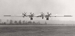
XB-35 early in its flight test program, still using its original contra-rotating
propellers. Notice that the spinners on the port side have been removed.
The
XB-35 early in its flight test program, still using its original contra-rotating
propellers. Notice that the spinners on the port side have been removed.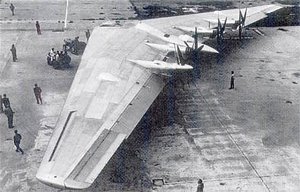
 The
XB-35's eight contra-rotating propellers seen to advantage.
The
XB-35's eight contra-rotating propellers seen to advantage.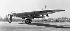 Side
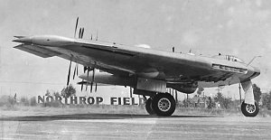
view of the XB-35 ready for takeoff, clearly showing the slots in the
leading edge. N-9M lineage is obvious here.
Side
view of the XB-35 ready for takeoff, clearly showing the slots in the
leading edge. N-9M lineage is obvious here.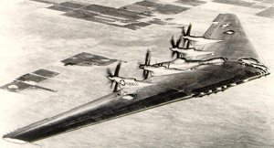
 Two
views of the
XB-35 on its maiden flight to Muroc Air
Field.
Two
views of the
XB-35 on its maiden flight to Muroc Air
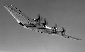
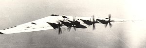
Field.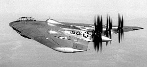 Another
view of the first XB-35 on its maiden flight, taken from its P-61 chase
plane. This view clearly shows its very high thrust line of 30 degrees.
Another
view of the first XB-35 on its maiden flight, taken from its P-61 chase
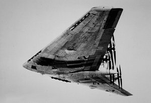
plane. This view clearly shows its very high thrust line of 30 degrees.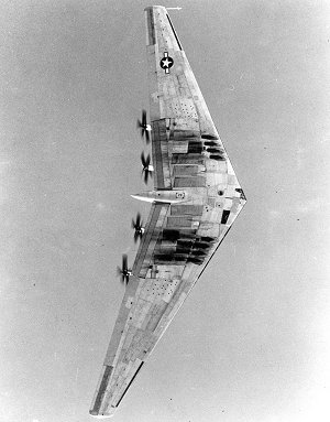 The
XB-35 passes overhead, showing the heavy exhaust stains on its underside.
The
XB-35 passes overhead, showing the heavy exhaust stains on its underside.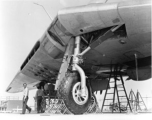 Nose
gear of the XB-35. Note the enclosed co-pilot's window above the strut, to
the right of the centerline.
Nose
gear of the XB-35. Note the enclosed co-pilot's window above the strut, to
the right of the centerline.
This website is conceived,
designed and maintained by BIS © 2006-2010 BIS Productions
Although every effort is made to make the information accurate, a mistake is
always possible.
Feel free to send an e-mail to correct or update any page of this site.